Toward the start of the 2011/2012 school year, my school’s mechanical autonomy group chose to at last disassemble some old FRC robots that had been gathering dust for six or seven years. We had no utilization for all the parts we peeled off the robots, so I liberally eased the group of a portion of these parts, including six Victor 884’s, six CIM engines (4x 2.5″, 2x 3″), 2 AndyMark Toughbox gearboxes, some #35 roller chain, and variety of sprockets, some steel shafts and shaft collars, a 1/4″ by 4″ by 3′ aluminum plate, 1″ aluminum U channel, 1/8″ polycarbonate sheet…. In any case, while looking into the CIM engine bends, and attempting to make sense of by the amount I could over-volt them, I ran into this, which at one point utilized a couple of CIM engines. That vehicle at that point drove me to these. By a fascinating incident, just half a month after I found those vehicles, I went to the Atlanta Mini Maker Faire, and think about what I saw there. In the wake of seeing the vehicles in real life, I chose to build my own electric vehicle, thus the thought for my scooter was conceived.
The scooter is designed for a top speed of around 25 mph, has around 3 drive, and can go 8-12 miles for every charge.
Stage 1: Parts and Tools
Here is a fundamental review of the most significant segments utilized. However much as could be expected I assembled the scooter with parts that I reused or as of now had close by, so a portion of these definite parts are might be elusive.
Giver kick scooter outline – mine was a Royce Union Transit
Wheels – I utilized 12.5″ low-speed pneumatic wheels from Northern Tool
Motor(s) – 3x CIM engines, which are commonly utilized in FIRST robots
Gearbox – CIM engines are genuinely rapid/low torque engines, so a gearbox was required notwithstanding the decrease from the chain drive. My franken-gearbox is a mashup of two Andy Mark Toughboxes from 2005.
Engine Controller + choke I went a piece pointless excess, and picked a Kelly KDS72200E, 72V, 120 A persistent, 200A pinnacle controller.
Batteries – 8 x Turnigy 5000 mAh 4s LiPo packs
Aluminum – point divert and level bar in an assortment of sizesd
Safeguards – 2x trail blazing bicycle back stuns, 2x off-road bicycle fork stuns
Stray pieces – an excessive number of and of an excessive number of various assortments to list here
1/2″ strung bar with coordinating nuts
1/2″ and 8mm hardened steel poles + shaft collars-for the turn focuses in the suspension
Enormous force switch
Breaker/Fuse holder
High present terminal connectors
Devices
Drill – with heaps of huge bits, up to in any event 1/2″
Hack Saw – in the event that you have a bandsaw with metal cutting sharp edges, if you don’t mind spare yourself and utilize that
Drill Press – Not carefully essential, yet it makes boring definitely adjusted openings a lot simpler than with a hand drill
Document – for smoothing sharp corners and expanding openings
Propane light and aluminum-zinc brazing poles
A grouping of clips
Seat bad habit – mine was truly a workbench that was a bad habit, however the benevolent that jolts onto a seat would be far and away superior
Fastening iron + patch – one with an overwhelming tip for welding enormous force connectors and battery leads
Lithium Polymer battery charger with power flexibly
At any rate two flexible wrenches
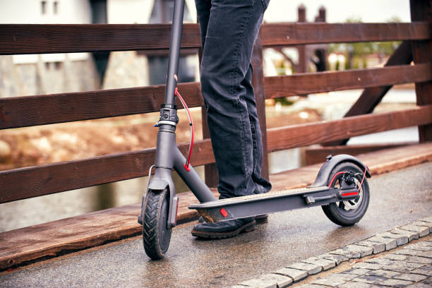
Stage 2: Donor Scooter Teardown and Layout
The scooter began as my old kick scooter, a Royce Union Transit, which was a little advance over the exemplary Razor scooters as far as quality – for example, it has front and back wheel suspension that utilizes genuine springs and safeguards instead of elastic squares, and it has an increasingly exquisite collapsing component.
I began by stripping the scooter of its unique haggles, with the goal that I could make sense of a rough design of the last scooter.
For use on milder and less customary landscapes than black-top, the first wheels expected to go. I got new ones from Norther Tool. They sell an adaptation with a 60t sprocket included, however I figured out how to rummage a 60t sprocket with a similar jolt opening example from my school. The best piece of these wheels is that I can later redesign the tires to these snowblower tires on the off chance that I need to utilize the scooter in day off.
To save space for suspension travel and keep a decent directing geometry, the wheels must be set totally under the deck of the scooter. This implies the rider’s foundation is well over a foot over the ground, and the leeway under the scooter is around 7 inches.
Stage 3: Rear Suspension Assembly
To suit the bigger wheels, I fabricated a totally new back suspension get together out of aluminum. I discovered some modest trail blazing bicycle safeguards on ebay, and purchased two with 1500 lb/in springs that I utilized for the back suspension. The principle casing of the get together was made from 1/4″ x 4″ lengths of aluminum bar, which, as the greater part of different parts utilized in the scooter, were searched from my outdated. Supports for the safeguards were made from 1/4″ x 2″ and 1″ U channel aluminum.
Since the first scooter had suspension, planned the new suspension framework to utilize a similar turn focuses as the former one. The first utilized 8mm jolts, and I had a few lengths of 8mm pure pole pulled structure old printers that turned into the new rotates. I found that one of the 8mm bars was flexing altogether under burden, so I penetrated out those openings to 1/2″, and supplanted the 8mm pole with a 1/2″ steel pole taken from an enormous level bed scanner.
I made the left arm of the suspension gathering around two inches longer than the correct arm, since I later would need to twist the aluminum around the back sprocket. To twist the monstrous aluminum bar without a hard core bowing brake, I warmed the region I expected to twist with a couple of propane lights, and afterward utilized a bad habit, clasps, and animal power to twist the metal.

Stage 4: Fork
Like the back suspension, the fork and front suspension required critical resizing to fit the new wheels.
For the new fork, I began by destroying the fork from an old trail blazing bicycle. Luckily, the scooter utilized a 1″ strung headset, which I was effectively ready to supplant with the off-road bicycle’s 1″ threadless headset.
I hauled the springs and dampers out of the trail blazing bicycle fork, and utilized them to make another pair of safeguards with turns at each end. The turns permitted me to build a main connection style suspension arm, which is a lot simpler to build than an extending fork.
I reused the fork crown and the highest point of the fork legs structure the off-road bicycle, and shot the 1/4″ x 2″ aluminum bars that made up the new fork to the highest points of the old fork legs.
In my unique fork plan, the front wheel was focused before the pivot of the directing section. While this structure accomplished work, I did a couple of human-controlled test rides of this setup and saw the dealing with as poor. The wheel’s forward position made it difficult to lean while turning, supposing that you incline toward a turn, the wheel normally needs to turn away from the turning heading. Also, at higher paces I understood that there would be the danger of the front wheel “castering” – attempting to turn around 180 degrees.
I revamped the fork, utilizing just the parts from the first cycle, with the goal that the front wheel was appropriately situated for good taking care of. This raised the front finish of the scooter several inches, however it was a value while tradeoff.
Stage 5: Wheels
To get the wheels to interface with the remainder of the scooter, I constructed my own axles our of 1/2″ strung bars and relating nuts. The wheel course’s inward distance across was 5/8″, so to get the 1/2″ hub to fit cozily through the heading, I made spacers by scraping down the sides of two 1/2″ nuts. The nuts are in a bad way towards one another until their ribs press against the outside of the wheel orientation. To secure the spacers, a subsequent nut was strung on for every one. At last, to bolt each wheel to the edge of the scooter, four additional nuts were utilized, two by two that squeezed against inverse sides of the aluminum outline pieces.
